Older analog generators work well, but since the readout is analog, they require an alignment to ensure the readout is accurate. And even then, it's not as easy to read the dial as it is to read a digital meter.
In this instance, I've also been using a frequency counter to determine if the generator is actually working. Now that I know it is, I'm going to check the accuracy of the reading and also see where the bottom end of each band is dropping out.
I've connected a Hewlett-Packard 5314A digital frequency counter to a point on the Hickok 288x where the output signal should be the strongest. This turns out to be pin 1, the first grid of V3, the 6SN7 frequency modulated oscillator and mixer tube.
In the picture on the left, you can see the blue cable that goes to the HP connected to the tube via a 470pf capacitor. The capacitor needs to be there in order to reduce the load on the signal so that the actual output isn't affected (shifted in frequency) by tapping the signal here.
This is just a temporary connection - I'll make it nice and tidy when I'm done.
At the other end of the cable is the counter. Here the Hickok is set to 2000 megahertz (mHz). See what I mean about having the counter connected? We can now twiddle the signal generator and we'll get a nice reading on the counter. Super convenient.
The question is, how accurate is this reading? Is the generator actually at that frequency?
An easy way to tell is to use a modern radio with a digital readout.
I used my trusty Grundig YB-400 to test. With the Grundig tuned to 2000 mHz and held near the Hickok, it picks up the signal. I know it's accurate because I get a 'zero beat' on the signal - the radio's tone changes to a lower frequency when it's right on. I can tune a bit higher (1999 mHz) or higher (2001 mHz) and the tone changes.
I test at some other random frequencies and get good results. Now I know that connection to the Hickok will work perfectly.
However, I'm still having an issue with the lower end of all the bands on the signal generator. What's happening is at a certain point, the generator stops working. Actually it just generates at about 950 kilocycles no matter what band it's tuned to. (By 'band,' there are different ranges of frequencies the generator will output on).
My guess is that the rotor vanes on the tuning capacitor are shorting to the stator at a certain point in their rotation.
This is pretty easy to see.
A little radio theory here: a radio selects a frequency to receive on via a "tuned circuit." This circuit is made up of a capacitor and a coil in parallel. The coil has fixed inductance, but the capacitor is variable so different frequencies can be selected. (The technical term for this is 'resonance.') It works the same way for a radio transmitter - frequencies that are transmitted on are selected in the same way. Our Hickok signal generator is actually a small low power transmitter.
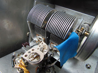
In the picture of the tuning capacitor above, it's open all the way. The rotor (the vanes that move) isn't meshed at all with the stator (the fixed vanes). The generator is tuned to it's highest potential frequency here.
As we rotate the frequency control, the variable capacitor (aka the tuning capacitor) is tuning the generator to a lower frequency.
There is a gap - literally an air gap - between the vanes of the capacitor that move and the static vanes. This is the very definition of capacitance - two charged plates spaced apart. Here we're varying the distance of the plates, and thereby, varying the capacitance, and also the frequency the generator (or radio...) is working on.
Cool stuff, huh?
Now we have the capacitor fully meshed - at the lowest range of frequencies. You can see that the gap between the vanes of the capacitor is very small. And if a couple of the rotors touched the stators, the cap would be shorted, and the capacitance would be "fixed" rather than variable.
And this is (I'm pretty confident) the reason why the generator is getting "stuck" at one frequency as it's tuned down.
I can see a couple of blades touching - I'll gently bend them so they won't short. I think that will fix the problem.
Good luck to me.


This is great, I know the post is an older post, but helpful. I just restored one of these and I like your idea about having the cable from pin one to gignal counter. This is a new product to me, so I was wondering after you connected the cable, how did you set your switch dials on the front of the 288x to get the correct frequency readout on your counter? I used a digital radio and the frequency tone response is spot on when looking at frequency dial. Its just the dials that are confusing (the correct combination).
ReplyDeleteI meant frequency counter not (misspelled "gignal" counter) LOL
ReplyDelete