It's pretty hefty - about 23 lbs., or 10.4 kilos in new measurement.
I like the two large dials for marker frequency and sweep frequency.
Here's a straight-on view.
This generator has a marker generator - which my Hickok 288X does not. Unfortunately, the Triplett is really designed for TV alignment - so much that the only way to get a 10.7 mHz marker is with a crystal. The marker covers up to 5 mHz, then jumps to 19.
Not a good thing for me, but I will get a crystal and it should be usable.
The two green arrows point to the mounting screws for the front panel. There are three other screws, but they just hold the faceplate on - they don't need to be undone to get the panel off.
The front panel is dented where the sweep output jack is located. I should be able to straighten that out.
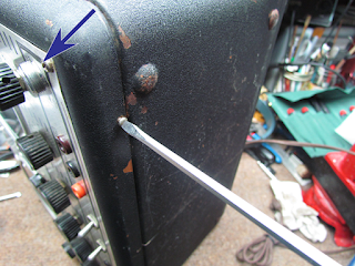
After undoing those two screws on the front panel, we remove the two screws on the bottom edge of the panel.
The blue arrow points to the jack again - you can really see from this angle how the panel is dented inward.
And finally there's a screw on the back of the cabinet that needs to be removed.
So far, we have not done anything difficult. Hopefully it will stay that way.
With the screws all removed, the front panel, with the chassis attached, comes away from the cabinet.
Wow.
That thing is amazing.
This is a pro-grade piece of kit.
All of the main components are housed in their own RFI-reducing boxes.
All of the sheet metal appears to be copper, or at least copper plated. Copper is probably the best material for blocking interference.
I don't see any scratches where plating has exposed an underlying layer of steel or other metal, so I'm pretty sure the chassis and the boxes are made from copper.
Very well done.
Note the filter can capacitor on the chassis - this will be restuffed with modern electrolytics.
Another hint about the chassis material are these places where paint has chipped off. There is copper underneath.
This is the underside. More of the same fantastic build.
The copper can on the lower left is where the AC power comes in - the can houses two coils to cut RF from the power line.
I'm going to recap the generator - there is an electrolytic can on the top of the chassis, another electrolytic you can see near the AC input can, and three wax-covered paper foil caps.
Those last 4 caps are in the audio output circuit - all the other capacitors in the generator circuits are mica or ceramic for stability.
And speaking of stability, there is a VR150 voltage regulator tube in the power supply.
This is a huge step above a Hickok generator.
Here's a peek inside the box containing the sweep circuitry. Very tidy.
On the upper left you can see the bottom of the can capacitor that we'll be removing and restuffing.
And this is the marker side of the circuit.
Notice also the grommets in any holes that wires pass through to prevent shorts to the chassis.
Really beautifully made.


0 comments:
Post a Comment