I finished the recapping on the Zenith last week.
Here's a shot of the recapped chassis. You can see the yellow poly caps and also the silver Russian K-40Y-9 paper-in-oil caps I used in the audio chain.
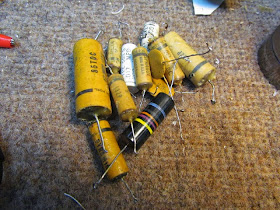
After you recap a radio, you wind up with a pile of old leaky caps. I'm going to save these in a small plastic bag and staple it inside the set.
I don't know why, the caps are bad. It's really just for historic value.
Now I'm going to do a full alignment on the set. I'm starting with the AM alignment - it's the most straightforward. The FM alignment is more involved, but I'll go through that too.
For this, I'll use my trusty Hickok 288X signal generator. This generator outputs both the AM and FM signals we'll need for the alignment.
Before I go much farther, I should mention what an "alignment" is. You may have heard this term and thought "what the heck is that?"
I'm skip most of the technical detail in this post; I really just want to give an overview of the process.
The best plain-language explanation I've read is in the Bryant and Cones Zenith Transoceanic book, which I'll paraphrase.
An alignment ensures the radio is playing up to its peak performance. That means that its sensitivity, selectivity and dial tracking are all at their optimum. If you think of the tuning circuits in the radio as a number of windows in sequential order, an alignment adjusts those windows so they all line up and the signal can pass through.
In brief, what we do is inject radio signals at specified frequencies into the circuit at various points, and adjust tuning coils or slugs in the set until the signal is at its strongest. That's it in short.
The tuning adjusters vary from radio to radio. They will be a screw or a hex slug of some sort. I have a couple sets of plastic adjustment tools so I can pretty much work on anything I'll come across.
The tools are plastic so they don't throw off the readings that we'll take. If they were metal, their capacitance would make the alignment inaccurate.
Here are a couple of the coils we'll adjust. Technically, these are IF, or intermediate frequency transformers. They consist of two coils and two threaded slugs that adjust up and down inside the rectangular 'box' you see.
I'm trying to avoid a lot of radio theory here (you can find it elsewhere on the interwebs...), but this is a critical adjustment with regards to the radio's sensitivity (how it picks up weak signals), as well as its selectivity (how well it rejects adjacent signals close to the one you want to pick up).
You can see the alignment tool has a hex-shaped end - this will fit into the slugs.
We set our intermediate frequency (IF) to 455 kHz. Most American sets use this frequency. You can find the IF on the schematic or alignment instructions.
I'm feeding the signal from the generator to a HP 5314A frequency counter. You may recall from my rebuild of the Hickok posts that I tapped a line from the inside of the generator to run to a counter, in addition to the RF output on the front panel. Comes in very handy since we can read the frequency at any time and keep the main output connected to the radio.
And with the generator connected per the alignment instructions, we adjust the slugs until they are peaked. How do we know when they're peaked?
We have a big VTVM (vacuum tube voltmeter) connected to the radio also. In the old days, the method was to connect the VTVM across the speaker terminals. That works, but you have to have the volume on the radio up all the way, and it screams a high pitched scream!
The modern method is to connect the meter to the AVC buss. You can have the volume turned all the way down and still get readings.
This is where a big meter is great. You can see the needle swing as you adjust the slugs, and see when you've peaked them up. You could use a modern DMM, but it's a lot harder to discern readings. The VTVM is the best tool for this work. Plus, it looks super cool!
In the old days, there were service manuals printed for all of these sets. In a number of cases, you'd even find the schematics and alignment instructions in the owner's manual. That material was important for the serviceman - since there were actually repair people, they would use this for troubleshooting. It's a real blessing for us modern restorers too. I have a set of CDs scanned from original manuals that have the repair information for hundreds of sets!
Next we'll do the FM alignment.


Hello
ReplyDeleteI'm interested in more photos of the underside of the chassis, I'm restoring one and the photos would be nice to review.
Thanks
David Walz
please use this email: david@wasillalocksmith.com
Wasilla Locksmith 907-315-0525