I believe I mentioned I had bought the PAS selector switch kit from Curcio Audio Engineering. Basically the kit is a new selector switch and enough wire to replace the old Dynaco switch and rewire the inputs.
It also converts the 'obsolete' (as they say) low-level Tape Head and Special inputs to high-level (aka line) inputs.
The conversion is very straightforward, and you don't necessarily need a kit - you could get a switch and wire and go at it. But I figured for my first time, I'd go with the kit and have everything in one place. The instructions are very well done and are helpful for doing this the first time.
First thing to do is to connect the right and left channel grounds to their own ground busses. This is done with uninsulated wire. I'm not sure why Joe Curcio recommends uninsulated, but he does, and I went with it. I will warn you that the holes in the ground connections are barely wide enough to connect two buss wires to them. The phono inputs don't get connected - they have a separate ground. Likewise, the phono inputs are run separate from the other inputs.
After the busses are done, you begin to wire the input leads. Here we use the Teflon-insulated 22 gauge silver plated copper wire supplied in the kit. The right channel is done first. I cut lengths off the twisted pairs I made earlier. Here's where the instructions are nice - they give the length to cut each lead.
After both channels are wired, install the new selector switch and connect the input lead to it.
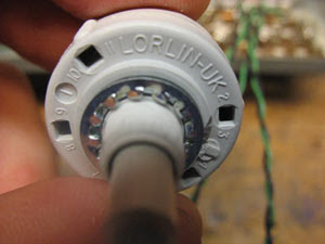
The switch is a very nice Lorlin unit. Very positive stops for all 6 positions. It bolts into the hole where the old Dyna switch was. Takes up much less room.
Here's the finished wiring. I tried to be as neat as possible. The red group are all of the inputs is for all of the right channel inputs, the tape input and output, and the preamp out. The green group is for all of the same connections for the left channel.
You'll notice a red and black and green and black set that are not grouped with the other leads. These are the phono inputs. They're kept separate to minimize hum and crosstalk from the other inputs. They basically just 'hang loose' from everything else and don't touch the chassis - if they do they could create a ground loop and produce hum.
The basic signal path for a line-level signal is this: it comes in through an input on the back panel, then goes to the selector switch. With the selector turned to the appropriate position, the signal is routed through the Blend Switch, and then to the input of PC-5, where it is amplified. Then it passes to the preamp outputs. Pretty simple. You can see why I wanted to remove the tone controls, the loudness switch and the filter switch - eliminating them means the signal takes a more direct path through the preamp, hopefully resulting in less degradation and better fidelity.
Phono signals are similar, but they go direct to PC-6, the phono board, where they are amplified. Then they take the same path through the selector switch, etc., as the line level signals do.


No comments:
Post a Comment