 I suspect this will be a long-ish post. I just uploaded 16 pictures!
Here we see the back of the c900 instrument panel on the bench in The Dungeon. I'm going to replace the electrolytic caps for the clock in hopes of getting it working again.
If you do a search for "repairing VDO clock" on the interwebs, you'll find quite a few posts about how to fix them in your vintage Yurrupean car. It seems the electrolytic caps dry up over time (surprise) and replacing them will fix the clock. Let's hope so.
The blue circuit board you see above is actually flexible plastic, and it's attached to the panel with plastic pins. The board has mating holes that just slip over the pins. I say this because I've seen some ads for used instrument panels on the interwebs saying "board is not lifting" as a sales pitch. For one thing, I find that hard to believe, since the whole thing is flexible. Second, it will lift in spots - it's just its nature. Doesn't mean anything is wrong with it. It's the way it was designed.
If it was glued down, it would be virtually impossible to service. And here I am proving that if the car lives long enough, it will need to be serviced eventually. (And many of these cars have very long service lives indeed).

You can remove this now or later. I opted to leave them until the end, since they hold the panel in place, which is handy while you undo the instrument and clock screws.
Obviously this is for a Saab 900, but the same basic approach should apply for any VDO instrument panel you may have in, say, a Mercedes, Porsche, BMW, VW, or that other Swedish brand that shall remain nameless.

See also the yellow arrows - they're the locations of the tach and clock screws which also must be removed.
This assembly is fairly fragile - handle it gently and put your screws in a safe place.
I also highly enourage you to wear vinyl or nitrile gloves when working on the instruments to avoid getting oils from your hands on them. You don't want to put it all back together and then see a fingerprint you left on the tachometer!

See what I mean about the circuit board? You can see a mounting pin to the right of the pliers, and you can also see how it lifts a bit up off the panel in places. It's the way it was made.


The circuit board material will flex enough to allow you to flip the tach up over the board backward. But be gentle!
The arrows in the picture show the three screws that hold the tach and clock face onto the white mounting piece. We need to remove them to get access to the electronics.

One note: the hands on the tach and the clock will shift some when you have it all opened up. Don't panic! They're just not mounted to anything now that the screws have been removed, so they will just spin around some. No big thing.
Handle the assembly with care - don't sit the face of the tach on something that will scratch it. I was able to sit it on the panel in a way that I wouldn't move while I worked on it, and it wouldn't shift and get damaged.

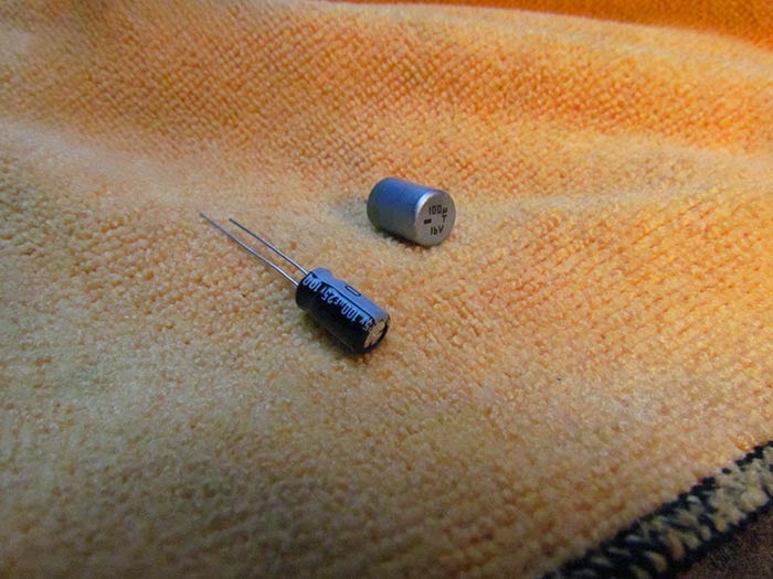
The new one is a bit thinner - and it's actually rated for 25 volts vs. the 16 volts of the original. Be sure to use a cap rated at 16 volts or higher.
I suspect a 35 volt cap might fit, but anything much higher will probably be too large.

I suggest using a good quality cap here - a cheap cap may fail and then you're back to square one. I try to use higher end Nichicons or Panasonic caps in stuff I build or repair. They cost just a few cents more than the cheap junk.

It looked like the board would slide out - there's a clip on the back. However, I couldn't budge it at all, and rather than risk breaking it, I just removed it from where it was. A little harder to get to, but not too difficult.

Note the little 'bins' where the warning lights shine through. Maybe I should pop the upshift (NOW! UPSHIFT NOW!) bulb out?
Nah, I pretty much ignore it anyway. :-)
Reassembly is pretty much the reverse of disassembly. The only semi-tricky part is getting the gauge to sit back down from where it came.
I found that if you gently move it around, it will find its seat easily.
Then put all the screws back in and button it up. Be sure to resolder the clock ground and put that tab connector back on.

It just unscrews from the panel.


Before I put the tach back in, I hit it with compressed air to get any dust off it. I also noticed there were small piles of dust on the inside of the panel where the clock setting knob and dimmer knobs pass through the plastic. (There's enough clearance that dust can get in.)
So I took a vacuum and compressed air and got all the dust out. Now it's perfectly clean inside.
Hopefully I'll have it back in place this week. I'm putting in a second, calibrated boost/vacuum gauge and will do that while I still have easy access to the factory hose behind the dash. Said gauge has yet to arrive at The Dungeon, so I'm in a holding pattern for now.
UPDATE 31 Oct 2014: The clock works! Replacing the caps is indeed the fix.
What a lovely thing to do to an old SAAB. That's the exact look of the dashboards I used to stare at. Shame the company went up the creek.
ReplyDeleteHello, I just completed this repair and haven't tested the cluster yet, but it would've been impossible without your detailed write up and photos. Only doubt I have is whether I got the polarity for the 47uF cap right, as I couldn't see any markings on the board. Regards from Barcelona and thanks again for this excellent write up!
ReplyDeleteThanks for your kind words. I'm so glad this helped!
ReplyDeleteAn easy way to check to polarity is with a multimeter/DMM. Since you know which is the negative side of one of the caps, that point on the circuit board will have continuity with the negative point (pad) on the board. Clip a lead to the known negative point, and touch the other lead to each of the two pads for the second cap. The negative will be where you have continuity (no resistance).
I'd suggest you don't apply power until you're sure. Otherwise, the cap will fail - meaning it will smoke, or worse, explode.
Hello, Barcelona here again. Just to say that it worked! Thanks so much!
ReplyDeleteExcellent! Congratulations!
ReplyDeleteThis comment has been removed by a blog administrator.
ReplyDelete